|
|
Bored Piles |
CFA Bored Piles |
Driven H Piles |
|
|
Advantages |
Bored pile are used to support multi-story building or bridges which can producing heavy vertical loads |
They are quick to install and have no requirement for temporary or permanent casings |
Driven piles are driven to a set in variable site conditions to achieve uniform minimum capacity with high reliability |
|
|
Methodology |
Pile drilled / soil removed and replaced with reinforced concrete |
Auger drilled into ground and replaced with concrete as the auger is removed |
Steel section driven into the ground |
|
|
Design |
Effect on adjacent ground |
No displacement of the soil but the potential for relaxation / softening adjacent ground, dependant upon the soil and bore support used |
Typically no displacement with good construction controls Localised densification of loose non-cohesive soils. |
Small cross sectional area and hence minimal soil displacement or potential improvement |
|
Typical size ranges |
450-2500mm diameter |
450 – 1200 mm diameter depths up to 32m |
150 – 350 UC’s, UBPs |
|
|
Capacity - Shaft friction |
Medium |
Medium |
Medium |
|
|
- End bearing |
Very high with enlarged base |
Medium |
High |
|
|
- Structural |
Very high structural capacity and stiffness achievable |
Cage insertion can limit tensile and flexural capacity at depth |
Driving stresses often govern the steel section required |
|
|
Durability |
Conventional concrete in the ground design Permanent liner in highly aggressive conditions |
Conventional concrete in the ground design |
Sacrificial thickness of steel above low groundwater level |
|
|
Construction |
Typical / Plant |
Hydraulic or crane mounted piling rig, handling crane, casing, vibro with powerpack and / or drilling support fluid plant |
Hydraulic piling rig, concrete pump and possible handling crane |
Crane, vibro hammer or hydraulic hammer with powerpack or drop hammer and leaders or guide frame |
|
Piling productivity |
16m deep - 600dia @ 2No/day in soft material including a 3m soft rock socket depth. Detailed production rates |
16m deep - 600dia @ 11No/day in soft material including a 3m soft rock socket depth |
16m deep - 350 UC’s @ 22No/day in soft material |
|
|
Material to Plant |
Concrete, reinforcement cages and method dependant material |
Concrete and reinforcement cages |
Steel sections |
|
|
Materials storage |
Casing and cage lay down area |
Cage lay down area |
H pile lay down area |
|
|
Noise |
Machine only unless driven casing |
Machine only |
Yes, if vibro used hammer used to obtain pile set |
|
|
Vibration |
No, unless driven casing used |
No |
Yes |
|
|
Spoil |
100% Nett volume |
100% Nett volume |
None |
|
|
Other |
Plunged columns can be placed into the top of the pile to structural positional tolerances |
Fast installation process with real time monitoring systems for construction control and records |
Full strength welded splice used at connections Predrilling can be used to overcome obstructions |
|
|
|
Driven Tubes Piles |
Precast Concrete Piles |
Vibro replacement |
|
|
Advantages |
They are ideally suited for marine and other near shore applications with a very high end bearing capability |
Precast driven piles can be environmentally friendly when construct temporary trestles in wetland |
Stone piles are a very effective technique, for resolving issues with liquefiable soils, that fall within the typical grain size range |
|
|
Methodology |
Tube driven using external or internal hammer and filled with reinforced concrete |
Pre cast section driven into the ground |
Soil displaced or removed and replaced with stone |
|
|
Design |
Effect on adjacent ground |
Large displacement of plugged tubes resulting in densification of non-cohesive soils and enhanced capacity |
Large displacement resulting in densification of non-cohesive soils and enhanced capacity |
Large displacement with densification of non-cohesive soils surrounding the stone column which enhances the capacity |
|
Typical size ranges |
350 – 750 mm diameter |
250 – 600 mm square |
600 – 1200 mm diameter |
|
|
Capacity - Shaft friction |
Medium |
Medium |
Low |
|
|
- End bearing |
Very high |
Very High |
Low |
|
|
- Structural |
Tubes can be reinforced concrete filled to enhance capacity |
Lifting, driving and jointing can limit capacity |
Stone quality & confinement in the soil limit the capacity |
|
|
Durability |
Sacrificial thickness of steel and internal reinforced concrete |
Conventional concrete in the ground design Review potential corrosion at joints |
Weathering / degradation of stone typically not an issue |
|
|
Construction |
Typical / Plant |
Crane, vibro hammer or hydraulic hammer with powerpack or drop hammer, leaders or guide frame |
Crane, hydraulic hammer with powerpack or drop hammer, leaders or guide frame |
Crane, vibro probe with power pack, water pumps, compressor and front loader |
|
Piling productivity |
16m deep - 600mm Dia piles @ 22No/day |
16m deep - 300mm square piles @ 20No/day |
12m deep @ 6No/day in soft material |
|
|
Material to Plant |
Steel tubes, reinforcement cages and concrete |
Precast concrete piles unless manufactured on site |
Stone |
|
|
Materials storage |
Tube and cage lay down area |
Precast pile lay down / curing area |
Stone stockpiles |
|
|
Noise |
Yes if top driven but limited if bottom driven |
Yes |
Machine only |
|
|
Vibration |
Yes |
Yes |
Yes |
|
|
Spoil |
None, but ground heave possible |
None, but ground heave possible |
20 - 100% Nett volume |
|
|
Other |
Predrilling can be used to overcome obstructions Enlarged bases can be formed to enhance capacity |
Variable pile founding depth can lead to high wastage levels and jointing expensive |
Top feed “Wet” process requires water circulation system and settlement ponds to contain silts |
|
|
Diaphragm Wall |
||||
|
Advantages |
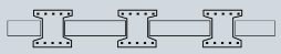
Sheet piles are best suited for the following applications temporary retaining walls, cofferdams and other temporary structures |
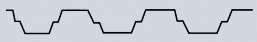
This is a permanent solution which provides increased wall stiffness compared to sheet piles |
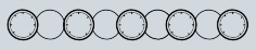
Diaphragm walls tend to be used for retaining very deep excavations as they can be designed to take very high structural loads |
|
|
Methodology |
Clutched sheet piles driven into position. |
A series of piles installed so that they overlap to form a wall. |
A series of interlocking reinforced concrete panels. |
|
|
Construction |
Establishment |
Cranes, vibros and hammers and / or pile jacking plant |
50-60T self erecting hydraulic drilling rigs and handling crane. |
50T crane + grab, handling crane, mud conditioning plant, mud storage |
|
Piling productivity |
16m deep - 600mm wide sheet piles @ 22No/day (in clay or sand materials) Detailed production rates |
16m deep - 600dia @ 4No/day in soft material including a 3m soft rock socket depth. Detailed production rates |
16m deep by 800mm wide @ 14-40m3/day of completed wall per rig per day |
|
|
Materials to site |
Sheet Piles |
Concrete, reinforcement cages |
Bentonite, reinforcement cages or concrete panels |
|
|
Work face access |
Plant & Materials delivery |
Plant & Materials delivery |
Plant materials and pipelines for mud circulation |
|
|
Noise |
Yes, unless jacked in |
Machine only |
Machine only |
|
|
Vibration |
Yes, unless jacked in |
No |
No |
|
|
Spoil |
No |
100% nett volume |
100% nett volume |
|
|
Product |
Wall Movement |
Flexible, can be increased with clutched king piles. More props or anchors can be used to reduce movements |
In-situ wall with ground supported throughout construction. Very stiff. |
Ground supported throughout excavation. Stiffest option given wall thickness |
|
Watertightness |
Good with joint treatment |
Groundwater control over pile length and satisfactory performance with some seepages |
Excellent over full depth of the wall with waterbar across panel joints. |
|
|
Connections |
Welded below capping beam level |
Drilled & grouted bars into piles, shear & bending capacity possible |
Full moment & shear connection via box-out and pull-out bars
|
|
|
Durability |
Internal painting and sacrificial thickness of steel |
Conventional concrete in the ground design. Internal lining for long-term seepage |
Conventional concrete in the ground design. No internal lining necessary |
|
|
Load Capacity |
Low end bearing capacity |
Capacity can be enhanced by increasing the length of some piles |
Wall has a large bearing area and individual panels can be extended |
|

|
Soldier Pile Wall |
Soilmix/Slurry Wall |
|||
|
Advantages |
Soldier pile and lagging walls are the most inexpensive systems compared to other retaining walls. They are also very easy and fast to construct |
Low cost and speed of construction for temporary and permanent retaining walls and soil support |
Excellent resistance to contaminated groundwater. They have abilityto adapt to ground movements such as earthquakes |
|
|
Methodology |
Constructed using piles timber infill panels (timber, steel or concrete) |
Series of bored piles installed relatively close together with shotcrete arches |
Steel or precast concrete elements placed in fluid soilmix / slurry |
|
|
Construction |
Establishment |
50-60T self erecting hydraulic drilling rigs and handling crane |
50-60T self erecting hydraulic drilling rigs, handling crane and concrete pumps |
50T crane + grab / CSM, handling crane / grout plant with screw feed silos, high pressure pumps |
|
Piling productivity |
16m deep - 300mm square piles @ 18No/day |
16m deep - 600dia @ 4No/day in soft material including a 3m soft rock socket depth. Detailed production rates |
16m deep by 800mm wide @ 20-50m3/day of completed wall per rig per day |
|
|
Materials to site |
Concrete, reinforcement cages, steel or precast concrete panels |
Concrete, reinforcement cages |
Cement, bentonite, steel or precast concrete panels |
|
|
Work face access |
Plant & Materials delivery |
Plant & Materials delivery |
Plant, materials and pipeline delivery of slurry |
|
|
Noise |
Yes, if driven sections |
Machine only |
Machine only |
|
|
Vibration |
Yes, if driven sections |
No |
No |
|
|
Spoil |
Dependant on installation method |
100% nett volume |
30%-80% Nett volume |
|
|
Product |
Wall Movement |
Ground unsupported allowing relaxation prior placement of panels and backfilling Stiffness depends on structural section and backfill compaction |
Ground unsupported allowing relaxation prior to concrete Finished product stiff |
Ground supported with stiffness dependant on steel section. Precast panels can increase stiffness. |
|
Watertightness |
Permeable with no groundwater control below excavation. Seepages long term |
Permeable until shotcrete in place with no groundwater control below. Seepages long term |
Good temporary performance due to replacement with CB slurry but some seepages |
|
|
Connections |
Numerous connection options dependant on materials used |
Drilled and grouted bars into piles, shear and bending capacity possible |
Welded to steel sections, shear & bending capacity possible. |
|
|
Durability |
Conventional concrete in the ground design or sacrificial steel thickness given long term seepage potential |
Conventional concrete in ground design |
Sacrificial thickness of steel and internal lining wall for long-term groundwater seepage |
|
|
Load Capacity |
Capacity can be enhanced by increasing the length of piles. |
Capacity can be enhanced by increasing the length of some piles. |
Capacity limited by penetration of steel beams |
|